During the course of their 20 years of service with the RAAF, CAC Wirraway aircraft were fitted with several different types of engine cowls.
There has been some confusion on this topic, particularly among scale modellers, which has been added to by a well-known kit manufacturer.
This short article is intended to remove any confusion about the types of cowls used and when they came into use.
Background
First, let’s look at the basic design of the engine cowling. The cowling wraps tightly around the outside ends of the cylinder heads of the radial Pratt & Whitney Wasp engine, working in combination with baffles between the cylinder heads to both cool the engine and provide forward thrust.
As with other members of the NA-16 family, the engine cowl on the NA-32 (NA-16-1A) demonstrator was constructed in two sections for easy installation and removal. The joint lines were roughly at 10 o’clock and four o’clock when viewing the aircraft from the front. The halves were officially described as “upper” and “lower” halves.
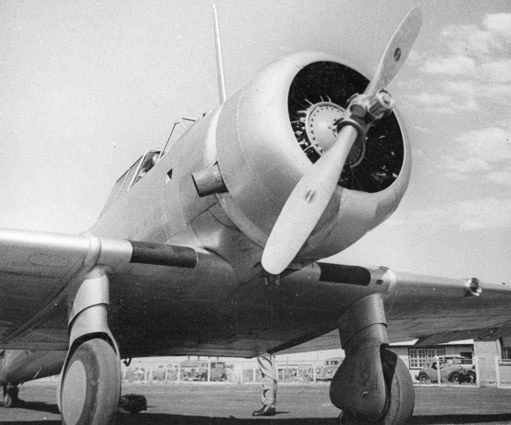
Clamps inside the cowl allowed it to be tightened against the cylinder heads, with heat-resistant felt pads between the cowl and the cylinder heads. The lower half of the cowl incorporated an intake for cold carburettor air (just inside the lower lip of the cowling) and a duct taking the cold carburettor air to the rear of the cowl. The duct protruded slightly below the underside of the cowl. Oil cooler air was drawn from the inside of the cowl via a duct between cylinders 2 and 3. This duct is sometimes visible in photos showing the port side of the aircraft.
The engine cowl on the NA-33 (NA-16-2K) demonstrator was longer than the cowl on the NA-32, since the NA-33 was fitted with a geared engine, as was the Wirraway. The engine cowling was of the same design, but extended by 4 inches to accommodate the longer engine. The lower cowl included the cold carburettor air intake and duct. Oil cooler air was taken from inside the cowl, but on the NA-33 two ducts lead to the oil cooler, one between cylinders 2 and 3 and the other between cylinders 3 and 4. The NA-33 also featured more louvres in the fuselage cowling to allow airflow out of the oil cooler.
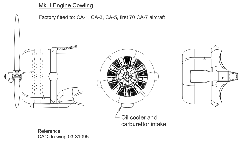
CA-1 Cowling
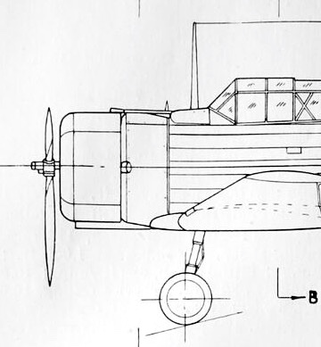
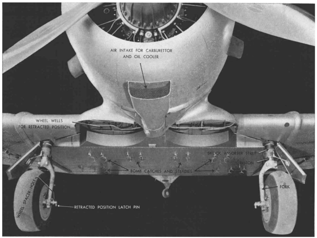
The adaptation of the NA-33 design to production as the Wirraway Mk. I included the addition an extra fixed gun in front of the pilot. This necessitated relocating the high-mounted oil cooler to a lower position, aft of the underside of the engine cowl, between the wheel wells. Therefore the cold carburettor air intake on the lower half of the cowl was modified to feed both the oil cooler as well as the cold carburettor air[1].
The front opening was enlarged and positioned below the cowl. When viewed from below, the intake duct was parallel for the first 11 inches and then tapered to match the diameter of the oil cooler. At the point of tapering, an internal duct led some of the airflow upwards to feed cold air to the carburettor via a mixing chamber, where the proportions of cold and hot air fed to the carburettor could be controlled by a butterfly valve actuated from inside the cockpit. A simple wire-mesh screen was fitted across the front of the air intake to prevent the ingress of foreign objects such as stones or leaves.
All Mk. I Wirraways produced under the CA-1 contract (A20-3 to A20-42) were fitted with this initial air intake design. Mk. II Wirraways produced under the CA-3, CA-5 contracts and the first 202 aircraft under the CA-7 contract (A20-43 to A20-203, delivered between 16/02/1940 and 24/12/1940) also featured this single air intake design.
Riverina Dust and Cylinder Wear
The air intake on the “CA-1 cowling” was adequate for engine cooling and air induction under most conditions, but the decision to locate several Service Flying Training Schools in the Riverina district of Southern New South Wales introduced an issue which the “CA-1 cowling” was not designed to accommodate. The runways at these Schools were unpaved paddocks, and dust quickly became a major problem for Wirraways operating in these conditions. This was particularly the case for No 5 SFTS at Uranquinty, where the largest number of Wirraways were based at one school. Fine particles of dust sucked into the carburettor made their way inside the cylinders, causing rapid wear of the pistons and cylinder liners.
CAC Service Engineer Ewart Chennery visited a number of RAAF units operating Wirraways to check on their performance and at the end of January 1942 he reported that only 14% of Wirraways at 5 SFTS were serviceable, mostly due to engine wear[2]. An engine overhaul workshop was also established at No. 5 Aircraft Depot, RAAF Forest Hill, near Wagga, to service worn engines. A similar problem arose with the Cheetah engines on Avro Ansons.
Numerous trials were carried out to solve this dust-ingestion problem, and several design changes were made to the air intakes and air cleaners in subsequent Wirraway production models.
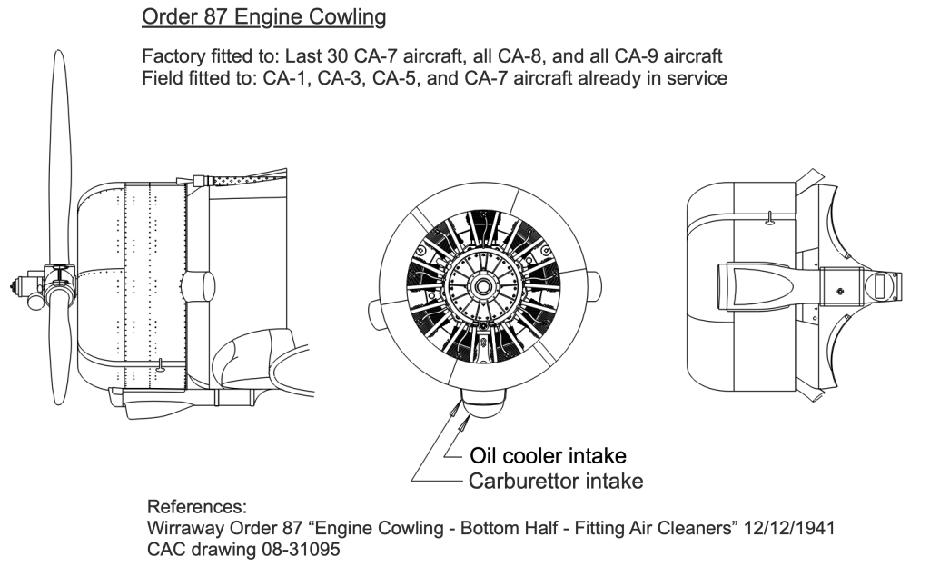
Order 87 Twin Air Scoop
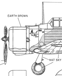
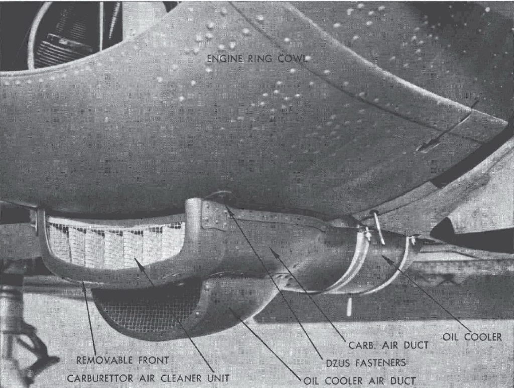
The first change to the air intakes in an attempt to resolve the issue of dust ingestion came in late 1940 with a redesigned lower cowl air scoop that incorporated a second air intake below the main intake. The second scoop fed air to the oil cooler, leaving the main scoop to supply only the cold carburettor air, and a filter element was added at the front of the main air scoop in an attempt to remove dust from air going to the engine induction system.
This modified air scoop design was fitted at the factory to the last 30 aircraft of the CA-7 contract (A20-204 to 234, delivered between 28/12/1940 and 26/3/1941).
This change was officially promulgated with the release of Wirraway Technical Order Number 87 Engine Cowling – Bottom Half – Fitting of Air Cleaners[3] on 12 December 1941. This Order briefly described “a modified type of bottom-half engine cowling in which an air cleaner is incorporated in the air scoop”. A filter element (“Cleaner Assembly”, part number 08-31016) was added behind the mesh screen on the main intake[4], which fed only the cold carburettor air, to remove dust from the incoming air.
This modified “Order 87 scoop” was also fitted at the factory to Mk. II aircraft delivered under the CA-8 and CA-9 contracts (A20-235 to A20-622, deliveries from 30/03/1941 to 21/06/1942).
The modified air scoop assembly was also fitted all aircraft already in service (A20-3 to 203) with replacement lower cowls shipped to units via No. 1 Aircraft Depot, Laverton.
Improvements did not stop with the “Order 87 Scoop”. An experimental air intake with filter was shown in the undated RAAF drawing A2554[5]. This was a modification of the “Order 87 Scoop”, with cold carburettor air taken from inside the lower lip of the cowling, rather than an external scoop. This was similar to the arrangement on the NA-32 and NA-33 cowls. Air for the oil cooler was still drawn in via the second (lower) intake.
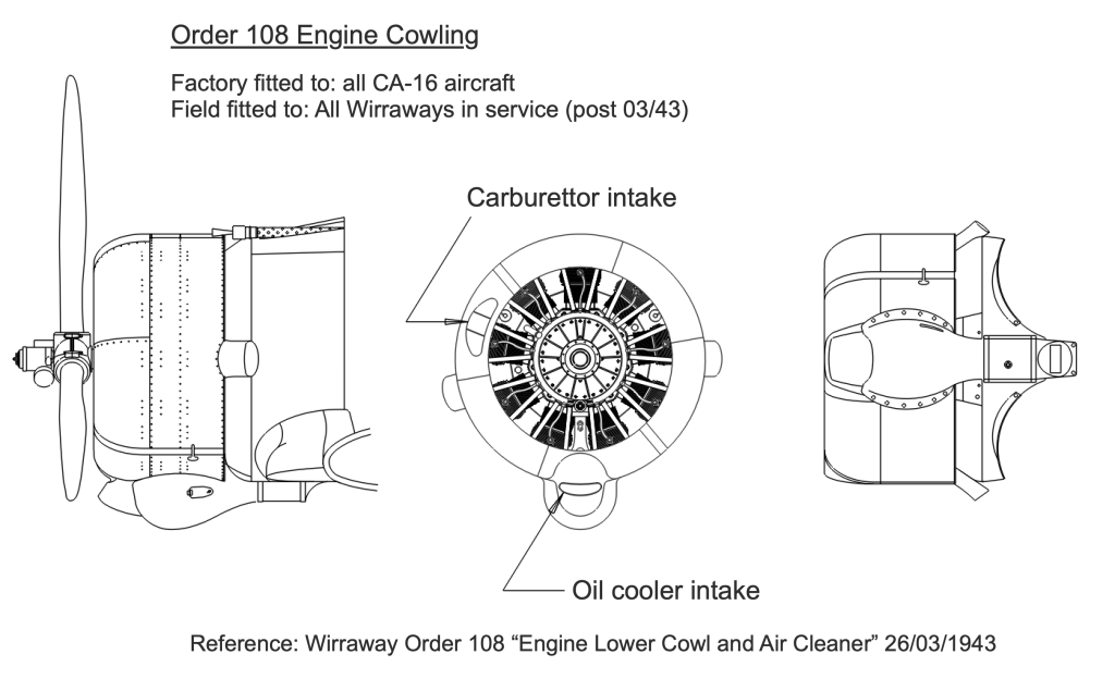
Order 108 Lower Cowling
By October 1942 a new design for the lower cowl was in progress following discussions between DTS, Lawrence Wackett and Ellis Wackett (AMEM). This design featured a raised intake and duct for carburettor air. The urgency of moving ahead with the installation of this new type of lower cowl resulted in a discussion by the Air Board on 19 November 1942[6]. ??? (AMSE) explained that the cylinder wear due to dust ingestion was costing in the vicinity of £5,000 per week for 8 months of the year, and 20-25% of this amount could be saved with the new type of filter. It was estimated that 500 sets would be required, at a total cost of £17,500 (£35 per aircraft). It was agreed by the Air Board that Ministerial approval be sought under War Cabinet minute No. 1573, and that DAP Demand 1034 for £17,500 be approved. Air Minister Arthur Drakeford approved the Air Board’s request on 26 November 1943. CAC modification 01-M3110 “Addition of Upper Scoop and Cleaner” provided the details of the modification.
Wirraway Order 108 Engine Lower Cowl and Air Cleaner – Modification was issued on 26 March 1943 and called for the lower engine cowl on all aircraft to be replaced with a new lower cowl incorporating a raised intake for cold carburettor air. The order applied to all Mk. I and II aircraft in service (A20-3 to A20-622 inclusive), with aircraft A20-623 and later (Mk. III aircraft delivered under the CA-16 contract) to be modified by the manufacturer as they were produced. New lower cowls were shipped direct to RAAF units from the supplier, Wunderlich Limited, in Sydney. Redundant lower cowls with the “CA-8 scoop” were packed in the delivery crates and shipped back to Wunderlich Limited.
The first Mk. III aircraft delivered under the CA-16 contract (A20-623) was delivered to the RAAF on 23/11/1943, fitted with an Order 108 lower cowling during final assembly.

The design of the Order 108 lower cowling incorporated several changes, relating to both improved carburettor air filtering and reducing accidental engine starting fires. The raised intake for cold carburettor air fed through a duct along the leading edge of the lower cowling down to a large bulbous chamber surrounding the air cleaner element. The bulbous chamber also served as a flame damper in the case of a back-fire during starting, often caused if too much fuel was primed into the engine prior to starting.
References:
[1] CAC drawing 03-31095 Assembly, Air Intake Scoop 23/05/1939
[2] Meggs, Australian-Built Aircraft and the Industry, Volume 2 Book 1, Echelon Starboard, 2020, p. 85 and p. 356
[3] NAA: A705, 150/4/1647, 1119874
[4] CAC drawing 08-31095 Assembly, Air Intake Scoop 29/11/1940
[5] NAA 440026
[6] NAA 24488837 Air Board Agenda 4416 (RAAF) Modification of lower half engine cowls on Wirraway aircraft – Department of Aircraft Production No. 1034